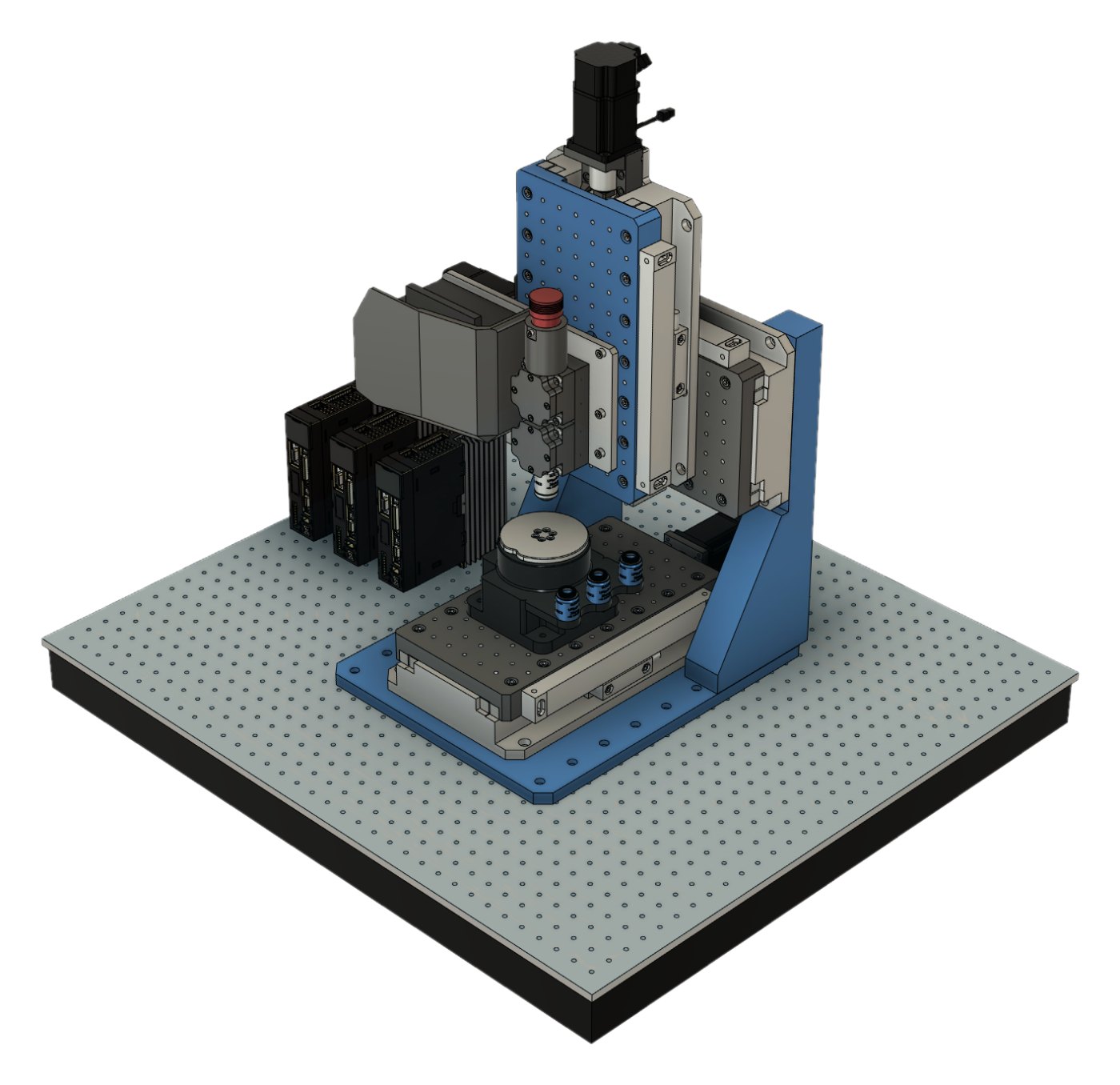
A precision 3-axis motion platform first; lithography is one configuration of it. Three identical linear modules make the XYZ gantry, and everything above the stage bolts to a standard optical-breadboard grid.
Every image on this page is a CAD render: Prototype 2.0 is in design. Its specifications are targets, carried over from what Prototype 1.0 measured.
Renders with dots are interactive: hover over or tap a part to see what it does.
In design · CAD stage
Optical tableA standard breadboard with M6 threads on a 25 mm grid, so ordinary optomechanics mounts right next to the machine.
Gantry frameTwo columns on a base plate carry the gantry axis and bolt down to the optical table.
Stage axisMoves the substrate. The same linear module as above: servo drive, ball screw, crossed-roller guides and an optical scale.
Gantry axisThe second horizontal axis, on the gantry. Together with the stage axis it gives at least 100 × 100 mm of XY travel.
Z axisThe same module mounted vertically: 40 mm of travel for focusing, with the exposure head on its carriage.
Servo drivesOne industrial servo drive per axis, all on a single CANopen bus.
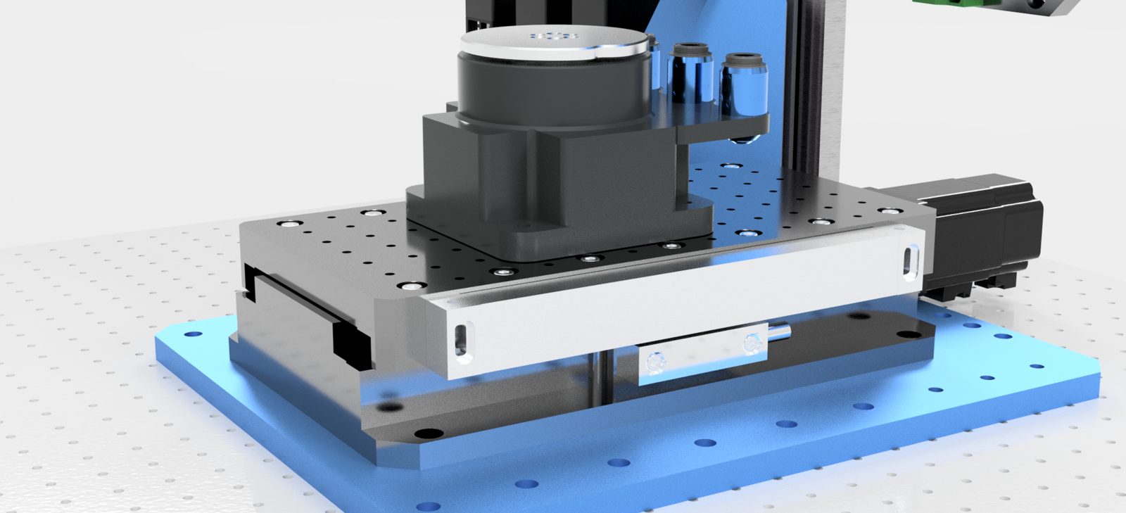
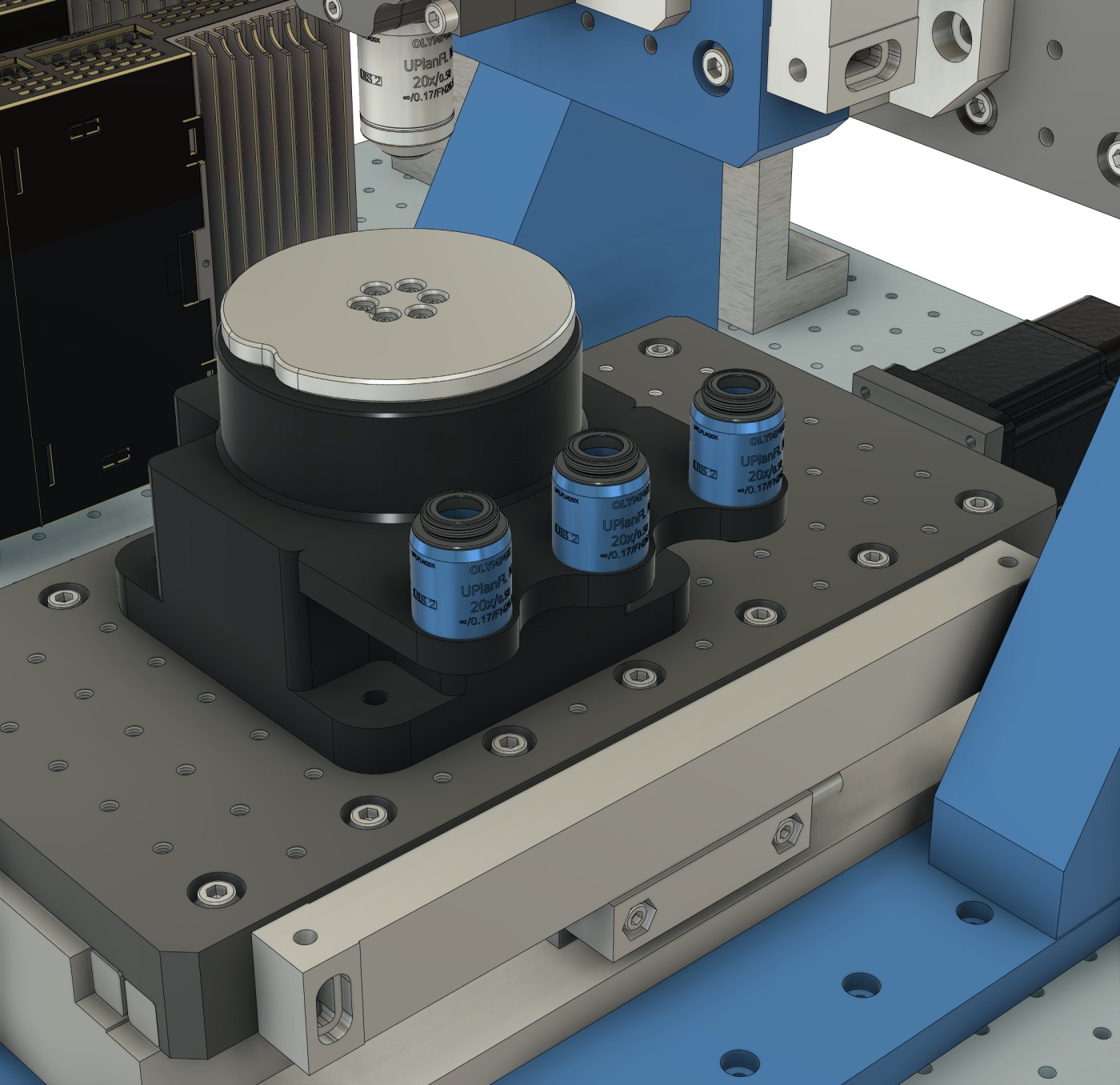
Chuck and objective rackA vacuum chuck on a rotary axis — in development — next to a rack for spare objectives.
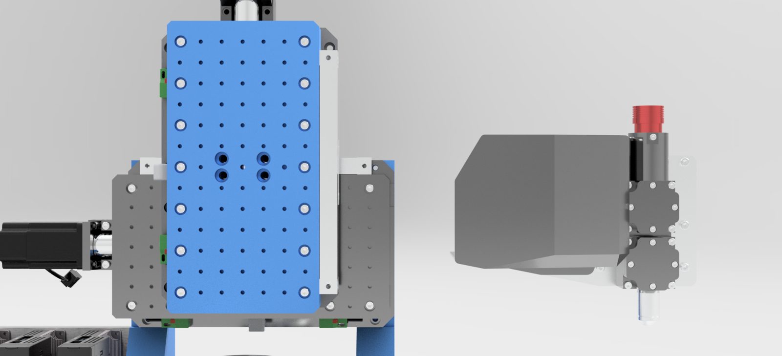
Exposure headDMD projection optics with a microscope objective; the camera looks through the same path. The whole head unbolts and can be replaced by other optics.
The whole platform: three copies of one linear module make the XYZ gantry, and the exposure head bolts to the Z carriage. Hover over or tap the dots.
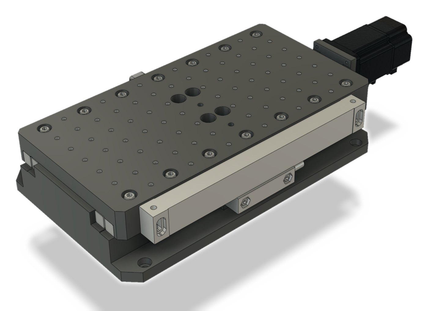
Sub-micron linear module
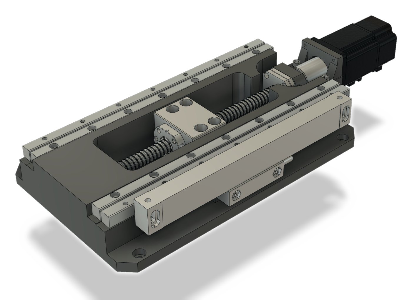
Every axis is the same block: servo drive, ball screw, crossed-roller guides and an optical scale, closed-loop and complete in itself — 100 nm as standard, 2.5 nm as an option. A product line of its own.
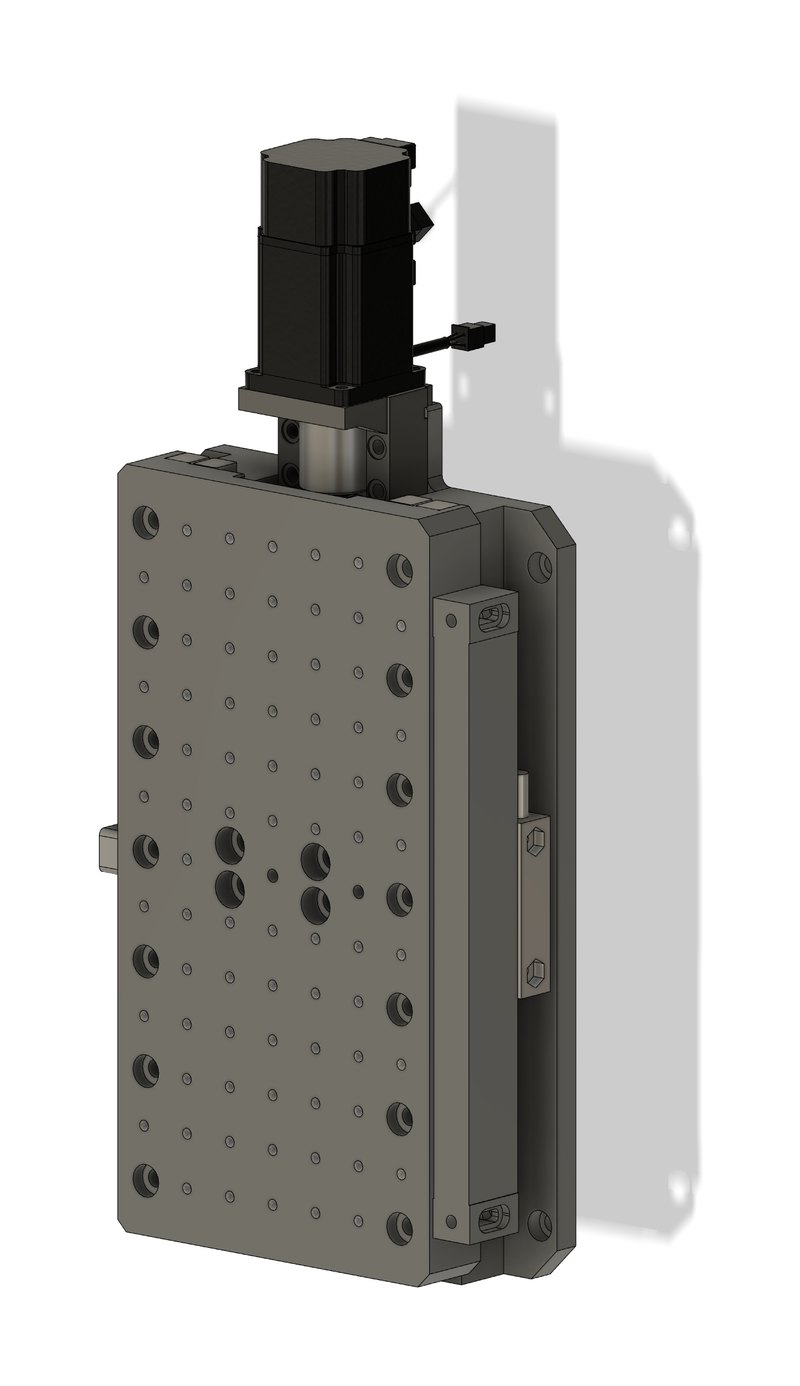
The same module works as the Z axis.
Base plateMachined base plate that carries the guides and bolts to a table, a frame or another module.
CarriageThe moving table. A 25 mm grid of M6×1 threads takes fixtures, optics or another module directly.
Optical linear scaleA glass scale with a read head measures where the carriage actually is, and the drive closes its loop on that reading — 100 nm as standard, 2.5 nm as an option.
Servo driveAC servo motor on an industrial CANopen bus. It turns the ball screw through a coupling.
Carriage with a 25 mm / M6 grid.
Base plateMachined base plate that carries the guides and bolts to a table, a frame or another module.
Crossed-roller guidesTwo pairs of crossed-roller rails carry the carriage: stiff, smooth and low in friction.
Ball screw and nutTurns the motor’s rotation into straight travel. The nut sits in a bracket under the carriage; the screw end runs in a fixed bearing support.
Optical linear scaleA glass scale with a read head measures where the carriage actually is, and the drive closes its loop on that reading — 100 nm as standard, 2.5 nm as an option.
Servo driveAC servo motor on an industrial CANopen bus. It turns the ball screw through a coupling.
Guides, ball screw and nut.Sealed optical scale along the axis.The exposure head unbolts and swaps for other optics.
Details
Substrate end: chuck and objectives
What changes against Prototype 1.0: an open gantry instead of a box, and every part of the optical path made swappable.
Stage axisMoves the substrate. The same linear module as above: servo drive, ball screw, crossed-roller guides and an optical scale.
Rotary base and objective magazineA compact motor under the chuck will turn the substrate for alignment — in development. The same housing holds the spare objectives.
Vacuum chuckHolds the substrate flat during exposure: silicon up to 4 inches, glass or PCB.
5× objectiveA wide field for finding the substrate and navigating over it.
10× objective10× / 0.5 NA: a larger exposure field per frame.
20× objective20× / 0.75 NA: the finest features, with a smaller field per frame.
The substrate end: chuck and a magazine of 5×, 10× and 20× objectives.
Your instrumentprobe stations, laser processing, AOI
Partnership
Looking for a manufacturing partner and investor
On the table: a working Prototype 1.0, the Prototype 2.0 design, full documentation and in-house software. A partner brings production, supply chain and market access; deal structure and investment size are open. Demonstrations and sample exposures by arrangement.